This
upgrade is a must for those who like to upgrade performance without
having the expense to play with anything else at all.
Hint: To help you access the ECU screws we suggest to remove
the Air intake hose which maybe in the way. As soon as you remove
the ECU cover I suggest installing a chip base so you can remove
the chip easily any time you want.
This
work can take about 1 hour to complete.
- Will
also give about 210 BHP and a little more torque +5% in low
and midrange
- Gives
very good drivability and is a very good and safe performance
upgrade for all SE/S4
This
chip is based on the improved S4s-Mk5-code but with +5% torque
(and similar top end power)
Is a very good choice like the improved S4s but with that additional
punch in low- and midrange
To help you with managing the ECU and getting a read out of the
errors and you require a program (freescan).You need a serial
cable to connect to you PC as we have. If you're unable to make
the cable please contact us for help.
To
install the chip simply follow the illustrated process on our
mods page
Road test:
The car was found to drive much smoother with noticeable lots
more power in the midrange area. This is a good start for all
stock Esprit's. Running chip #2 gives you more refined running
and extra performance and an all-round better Esprit over the
stock chip. This would also benefit those who run their Esprit's
all year round.
Chip
#2 is available from our parts page.
We
recommend continuing to the second stage to benefit from the ECU
upgrade.
STAGE 2 Air intake and Air box Filter
Parts
used:
- Air
box ram air Modification
- K&N
Filter
- Oil
catch tank
- Chip
#2
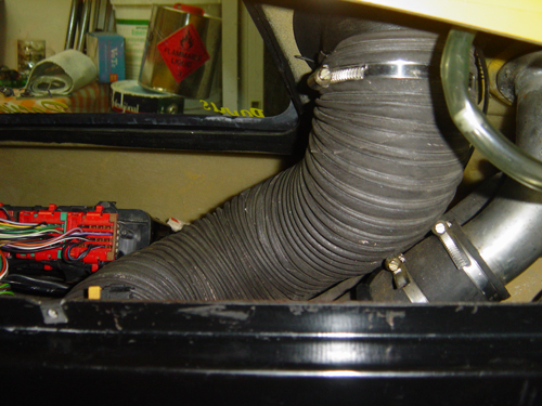
Not
all Esprits use the same air ram intake size pipe, depending on
the year of manufacturing as Lotus factored forever made updates
while the vehicle was on the assembly line as to be expected,
lucky enough ours had 100mm intake hoses pipes across the air
assembly. So we only had to cut it a little shorter to rich from
the intake from the body air intake panel directly to the air
box and by past all the unnecessary loops (Usually the factory
directs this hose to an area at the right quarter panel which
causes the fresh air to go for a long trip and back with a another
hose to the air box. This modification can take about 30 minutes
to complete. However if your model has got an inlet smaller then
100mm you just have to make it up with any pipes you can find
or make a mold out of fiberglass.
This
illustrated process is available on our upgrades
page
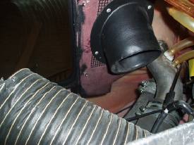
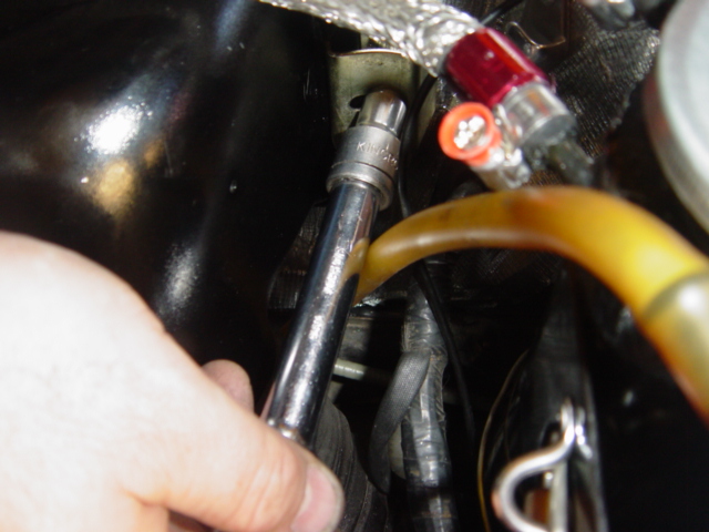
Note: Be careful not to knock out of place any of the black thin
vacuum pipes especially the one to the map sensor (see pic below)
otherwise you will experience a very bad start to the car with
code 33 error and possibly and "check engine warning light
displaying.
Note
the position of the vacuum hose on the map sensor located under
the right guard
K&N Filter: We managed to score the correct size K&N
filter for the job as I found out they are sometimes hard to get
but now available on our parts list page. This unit should last
for a very long time in fact some people claim possibly for the
life of the car, as the only requirement is cleaning it.
To
get to the filter you need to remove the Air intake hose to the
Turbocharger unit and the 2 x 10mm bolts on both sides of the
Airbox.
Note:
Make sure to use the original rubber seal from the old filter
as the K&N filter does not come with one.
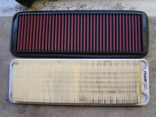 <Original and K&N air filter
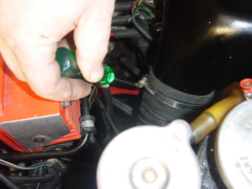
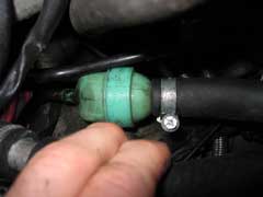
Oil
Catch Tank: High performance engines and race cars are routinely
fitted with catch tanks to collect oil mist that is produced by
pressurisation of the sump.On the Esprit there is an oil/air separator
(Green plastic thing, see below) which is supposed to trap all
the oil and feed it back to the sump.
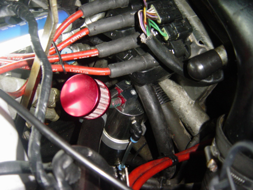
We recommend to find a good place for your Oil catch tank before
you start cutting or disconnecting hoses. Since we don't like
drilling the Air box to fit the tank as its been suggested by
others we decided to place it a little lower (see pic below).
The catch tank was fitted by Steve Tailor from " The elan
factory" in a lower more natural position for any oil deposit
to flow through properly as gravity is important to this mod.
If
you are happy with it's resting place, disconnect the thick oil
breather hose going to the air box and extended with your choice
of hose into the catch tank if you require, ours did not need
an extension only a small step down hose to connect properly to
the tanks fitting.
You
will need to block the fitting where the hose attached on the
air box using a plug (see pic below). We also installed a breather
filter to the oil catch tank since it must be able to breath.
Note:
This modification does may not comply with road regulation in
some countries including Australia. Your other choice to comply
is to fit the breather oil catch tank hose back into the Airbox.
This
process is illustrated in our mods page.
This process is referenced from LEW. LEW has used a different
unit than ours but you will get the idea.
If there is any interest in this Catch Tank Kit, then it can be
supplied as a package by us. e-mail
us for details.
Road
test result:
This
completes the 1 stage of the project. We road test the vehicle
with a K&N Air filter installed and the car felt and sound
so much more like a super car. You can hear the turbo and Air
box working well that's if you don't mind those kinds of sounds,
the power and power response feels like it has increase up to
20%. We can now notice wheel spin after 3000 revs, power is almost
constant during the rev range, some turbo delay is to be expected
however this should be solved on the next stage.
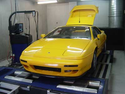
Dyno results: 203BHP
Note:
measuring Horse Power at the wheels. (on 4rth Gear)
On
a dyno you will always see very strange Hp-figures when you put
an Esprit on it. The main reason for this is the fact that MAT
(= mass air temp) and coolant temp will be too high on a dyno
and for that reason the ECM will retard ignition and as a next
step it will also lower max. boost. There are also some other
parameters that will have an influence especially when you do
these dyno runs. For all the above reasons the final figure on
Horse Power can differ up to 40% less from what the vehicle can
do on the road.
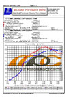
DYNO Graph
ECU Chip #2
STAGE
3
-
Chip # 5installation.
-
Manifold updates
- DUMP
VALVE (BOV)
- Fuel
Injector service/test
- Back
Pressure Valve
Installing
a BOV at this stage the Esprit will perform better through changing
gears by reducing turbo lag. The turbo will also spin up quicker
when back on the throttle as it will now keep spinning. This kit
will also protect your turbo from wear, by releasing pressure
which would normally stall the turbo causing increase wear and
tear.
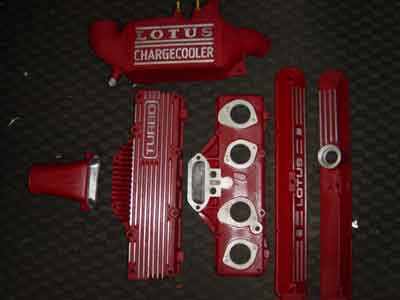
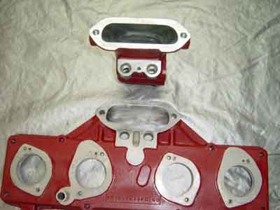
However
we have done some cosmetic work to the inlet manifold after consulting
with many experts regarding powder coating the area, however powder
coating was not recommenced for our project due to the heat transfer
characteristics the coating provides and remember we are trying
to cool the area as much as possible here, so we ended up with
the next best solution of plastic media blasting which
was done by CAR-STRIP in Melbourne. Plastic media blasting
apparently does not leave any particles which can harm the engine
and its also easy to clean with water after the process has finished.
We finished the job with a special red
VHT wrinkle paint and PPC
protective clear coating for the inlet manifold.

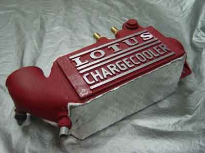
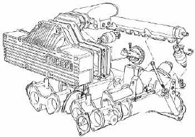
The
4-cylinder models (SE, S4, S4s & GT3) use an air/water heat
exchanger (chargecooler) to reduce the air inlet temperatures
and so increase the density of air leaving the turbocharger compressor
before it enters the intake plenum chamber. The chargecooler is
flexibly mounted to the engine, and uses flexible high temperature
hoses to connect the intake and outlet to the compressor and plenum
respectively. Air passing through the chargecooler flows past
a matrix of tubes through which water is circulated in a closed
system by an engine driven pump. Heat is transferred from the
intake charge air to the water which is pumped via alloy pipes
routed through the chassis backbone, to a chargecooler radiator
mounted ahead of both the air conditioning condenser and the engine
cooling radiator.
The
system is prone to many problems and it is vital for the optimum
performance of your car that this system is in tip top condition.
Lowering the inlet air temperature is a very safe and easy way
to increase engine performance. You gain approx. 0.5 - 1 hp for
every 1 °C you can lower the inlet air temperature.
Our
initial upgrade is to achieve a better results with the factory
assembly. Revolution Racegear provided us with a special
heatshield material for the chargecooler, this product provided
sufficient heat protection from the T3 turbo generating heat using
the stock pump. All these products worked well supporting the
heat transfer we wanted to achieve and help the engine to run
cooler.
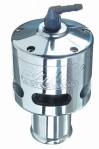
Our
team is also working on a temperature controlled Johnson
CM30P7-1, Part Number 10-24504-03, 12V which we will test
on a later day.
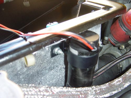
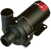
*
Recommended position for the Johnson pump (no need to drill the
body. Use the solenoid screws coming through the boot panel
The
Johnson pump can be wired to the system a couple of ways showing
in our upgrades page and more importantly
this solution is also supported by Lotus Factory. However our
team will develop a temperature controlled circuit at a later
stage to improve the operation of this system even more, this
mod will help the chargecooler to run at its optimum temperature
while circulating the water as the engine requires during higher
temperatures. That way the pump will not run at full power as
per the original tests. This pump was tested at 30lts/min.
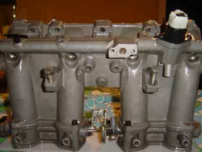
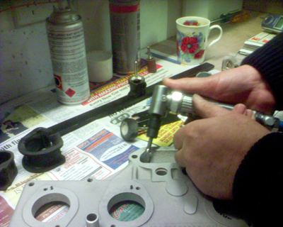
We
suggest if you ever get to this stage to also improve the internal
surface of the manifold, there is a lot of air flow lost from
the turbo to the throttle body inlets. International tests have
shown that the standard inlet system lost over 30 cfm of airflow
from turbo to the inlet ports. However with a little matching
up of the inlet manifold to the ports, gas flowing the nozzle
and plenum you could get this down to about 7-8 cfm loss. The
entry of the nozzle to the plenum is quite restrictive.
Over 5mm can be machined from the entry of the nozzle to the plenum
and all the edges can be reduced off and matched to the individual
gaskets. Thanks to Steve from "The elan factory" showing
us the way it's done. Next step is to polish the manifold internals
and cut the casket to the new shape of the manifold, this will
help to gain the air flow and complete the job right.
Fuel
Injectors Service: Both
stock primary and secondary (Bosh) injectors were tested and passed.
At this stage we will not make any upgrades to the injection system
till we complete all the dyno stages. In case of an upgrade the
only recommendation is to replace only the secondary injectors
(see stage 6) as the primary will work very well up to 350+ HP.
Stock
Secondary Injectors measured at 17ml flow, Primary Stock Injectors
should be at 36ml flow
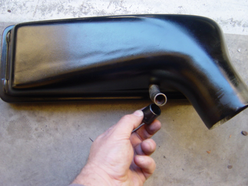
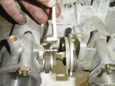
Back Pressure Valve: Since we had clear view to the inlet
manifold during this stage we were able to remove the exhaust
back pressure valve assembly attached on the manifold including
the pivot arm showing on the picture below. We also had to make
the appropriate modifications to the vacuum lines to trick the
ECU that the system is still connected.
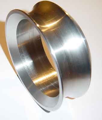
You will also need to install a spacer at the exhaust where the
back pressure valve is located as the valve will now be closed
(Don't go anywhere before you do this) If you don't have the appropriate
exhaust spacer at the time you can wire the valve open for the
time been to hold the butterfly open or If you don't want to install
the spacer you can also take the butterfly off from the assembly
which will cause you to disconnect part of the exhaust to get
to it and remove the butterfly from the assembly. If you are able
to do this you can re install the original butterfly body back
to its original position to act as an spacer this time.
Exhaust
spacer is available from our parts list
part seen below.
This
process is illustrated on the mods page.
Road Test: The first thing we notice is all the
new sounds coming from the BOV valve and the Airbox. it's like
driving a different vehicle, this is not quite car any more and
it takes time to get used to from the stock system, forget about
turning the stereo on there is a better song at the back end.
The power is more noticeable at the top end as the boost has been
increased so plenty of pull from the 2.2ltr engine.
Dyno
results:
209 BHP
Note:
measuring Horse Power at the rear wheels. (on 4rth Gear)
On
a dyno you will always see very strange Hp-figures when you put
an Esprit on it. The main reason for this is the fact that MAT
(= mass air temp) and coolant temp will be too high on a dyno
(up to 20 degrees celcius noted in our tests.)and for that reason
the ECM may retard ignition and as a next step it will also lower
max. boost. There are also some other parameters that will have
an influence especially when you do these dyno runs. For all the
above reasons the final figure on Horse Power can differ up to
40% less from what the vehicle can do on the road.
NOTE:
This tests were focused on the performance produced by #5 ECU
ship installed in a stock engine with the original Exhaust system.
DYNO
Graph
Chip #5 results
STAGE 4
Parts
installed: (Mark I) Sports EXHAUST SYSTEM fitted with a Catalyst
testing Chip#2 and #5 with a K&N filter.
Road
Test: The car was much stronger across the rev range with
the turbo coming a little faster. The sound of this system is
perfect for those who don't want to attract to much attention.
This system is totally legal and now the car sounds as it should.
Dyno
Results: 227 BHP
ECU
Chip #2 and #5 with the Mark I sports exhaust system produced
clearly 218 and 227 BHP. See more detailed tests with many other
ECU chip configurations in our Exhaust
page
DYNO
Graph ECU
Chip #2 Vs #5
STAGE
5
Parts
Installed: ECU PROM UPGRADES Chip#6, (Mark I) Sports EXHAUST SYSTEM
fitted with a Catalyst, K&N filter.
Road
Test: This is the first time that we noticed considerable
deference in Horse Power using deferent chips. The #6 chip is
the way to go for maximum performance however it will require
some extra mods to the fuel injection as we have noticed the car
running lean across the rev range and the turbo lucking of top
end power due to its factory limitations. This was expected ....!!!
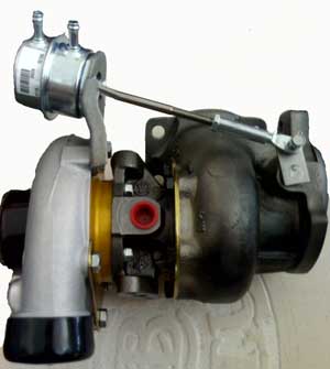
Factory
Turbo
The 1990-1993 SE and 1993-1996 S4 were fitted with a Garrett T3
with a 40 or 50 trim compressor wheel. It has a maximum flow rating
of 30 lbs/min at a pressure ratio of 2.2 (1.2 bar boost) with
58% efficiency.
The bottom line is that once you start producing a very free flowing
engine setup; air filter, ram air mod, exhaust mod, de-cat pipe
the turbo then become the weak link in the system. The turbo in
the S4 cannot flow enough air at the top end, the result is that
the inlet temperature (MAT) raises very dramatically and boost
drops away. In fact there is a condition in which increasing the
boost will actually produce lest power this is clearly demonstrated
from the graph below.
As
mention above the graph is also showing drop of power due to fuel
starvation which will be fixed on the next stage.
Dyno Results: 247 BHP Stock turbocharger
Dyno
graph ECU Chip #5 Vs #6 with a factory turbocharger.
Stage
6
Parts
Used: High Flow Turbo, high volume secondary injectors, (Mark
I) Sports EXHAUST SYSTEM fitted with a Catalyst, K&N filter,
High pressure fuel pump.
Fuel
injectors _ Secondary: Although
the two plenum secondary injectors are similar in construction
to the primary injectors they are actually high impedance (16
ohm) 190 cc/min or 18 lb/hr saturated type injectors. These injectors
operate at a fixed frequency of 128 Hz, with the quantity of fuel
delivered dependent only the pulse width sent by the ECU.
The
stock S4 ECU fuel mapping only triggers the secondary injectors
over 4800 rpm and 0.7 bar boost. We have fitted 270 cc/min (25.7
lb/hr) RC Racing high impedance injectors. If you are undertaking
major engine mods it is very important to think about the correct
fueling.
The
ECU goes into "open loop" mode above 94% throttle openings, in
open loop mode there is no feedback to the ECU from the lambda
sensor, under these conditions fueling is based on pre-stored
fuel maps in the ECU.
Our
first Dyno run with the new local made experiment turbocharger
and secondary injectors showed the engine running lean across
all the rev range. At that stage we introduced a high pressure
fuel pump to correct this issue.
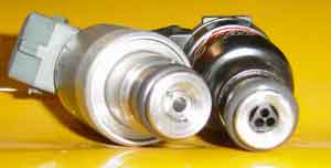 <
Secondary Injectors
<
Secondary Injectors
Picture above is an image of the 2 secondary RC
injectors on the bottom compared to the standard Lotus Bosch injectors.
High
pressure fuel pump: As
shown in the previews Dyno graph at this stage the vehicle is
showing running lean at the top end. To correct this we have installed
a local supplied high pressure racing fuel pump can support engine
up to 450 HP.
The
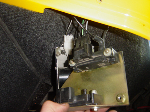
standard S4 fuel pump is a roller vane type, high pressure electric
fuel pump mounted within the right hand fuel tank. The pump supplies
fuel at 30.5-55psi to the fuel rail. On the Sport 300 the fuel
pump was upgraded to a higher capacity pump as fuel starvation
was experienced in testing. Unfortunately the Sport 300 pump is
now obsolete and so an alternative up rated delivery compatible
in-tank pump was purchased locally.
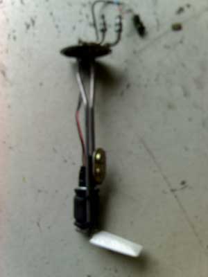 <
High Pressure Fuel Pump.
<
High Pressure Fuel Pump.
The
removal and installation of the pump is available here.
TURBOCHARGER
UPGRADE RESULTS
After
8 months R&D and testing recommended solution on turbocharger
units available, our team has installed a ball bearing unit modified
locally to produce the minimum satisfactory results used on a
stock internals engine producing 250 HP at the wheels on the dyno.
We
noticed a better performance on the road as the Mat sensor is
running much cooler producing an estimated 20 HP more due to cooler
Mat temp.
On
the dyno the car was much stronger and delivery smoother power
in the top end.
However
we will continue testing all the solutions available in the near
future to improve the results we have achieved using our local
and overseas experts/suppliers.
Over
all including stage #6 we have managed to increase the HP power
of a stock internal engine by 40% by adding the quality parts
as shown above. We will be happy to discuss any of your upgrades
or concerns with you regarding any of the stages shown.
 More info on the turbo results